
Controlling an LED matrix for mimicking cell-free expression
To go beyond just handling tubes and liquids and to engage fully in the process from designing, planning, handling and monitoring biological parts we created a set of simple open-source tools to create your own bio-pixel display ‘bi.xel’.
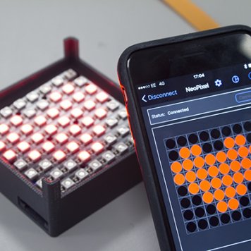
In this tutorial you learn how to create a simple led-matrix and use an app to allow you to design your 8x8 pixel picture choosing different colors (colors stand for the circuit you choose). The little device lets you place your PCR tubes on top to mimic the bio-pixel display and will allow in the future to further functions for educational purpose.
Before you begin, here some useful links:
•NeoPixel Uberguide
•Adafruit Feather 32u4 Bluefruit LE
•Battery Powering Wearable Electronics
•Adafruit Guide to Excellent Soldering
For this project you will need:
•1x Adafruit NeoPixel LED Matrix 8x8
•Bluefruit Feather 32u4
•Lithium Ion Polymer Battery
•3D printer or Thingiverse
•Lasercutter
•4mm acrylic sheet (min 10x10 cm)
•Adafruit Bluefruit LE Connect app for iOS or Android
•PCR tubes
•Micro-USB to USB cable
•Soldering and breadboarding stuff
Electronic parts for Bi.xels One of the best ways to create open-source electronic prototypes to create interactive electronic objects is Arduino. If you are not familiar with Arduino here a first introduction.
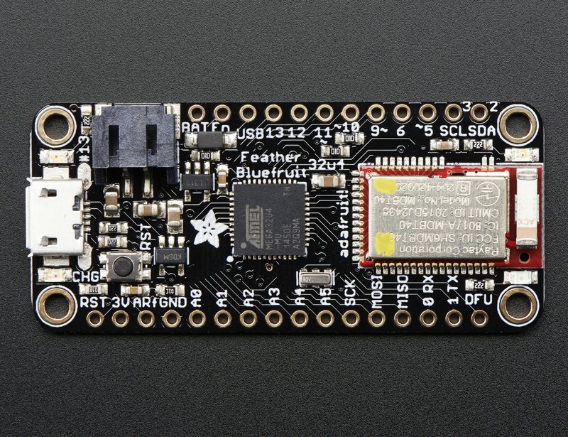
In our case we will use the Bluefruit Feather 32u4 for our bio-pixel modeller which is an Arduino compatible board from Adafruit, another very useful open-source platform and supplier for DIY electronics and kits.
The Bluefruit Feather 32u4 is particular useful for small devices that are connected to a smartphone to send and receive data with it.
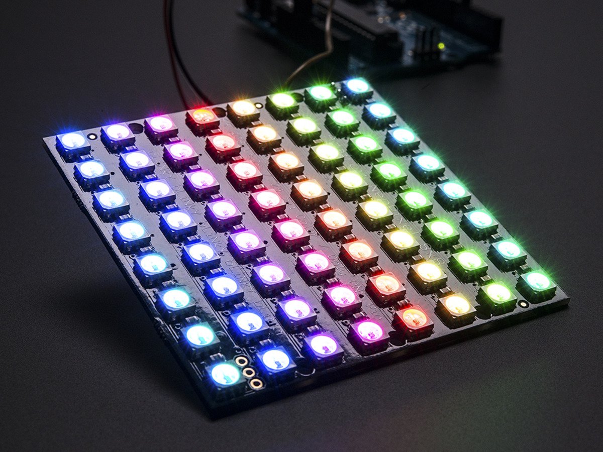
To animate the reaction of our our 8x8 bio-pixels, we are using the Adafruit NeoPixel NeoMatrix, another very popular item from Adafruit and just one possible form factor from many.
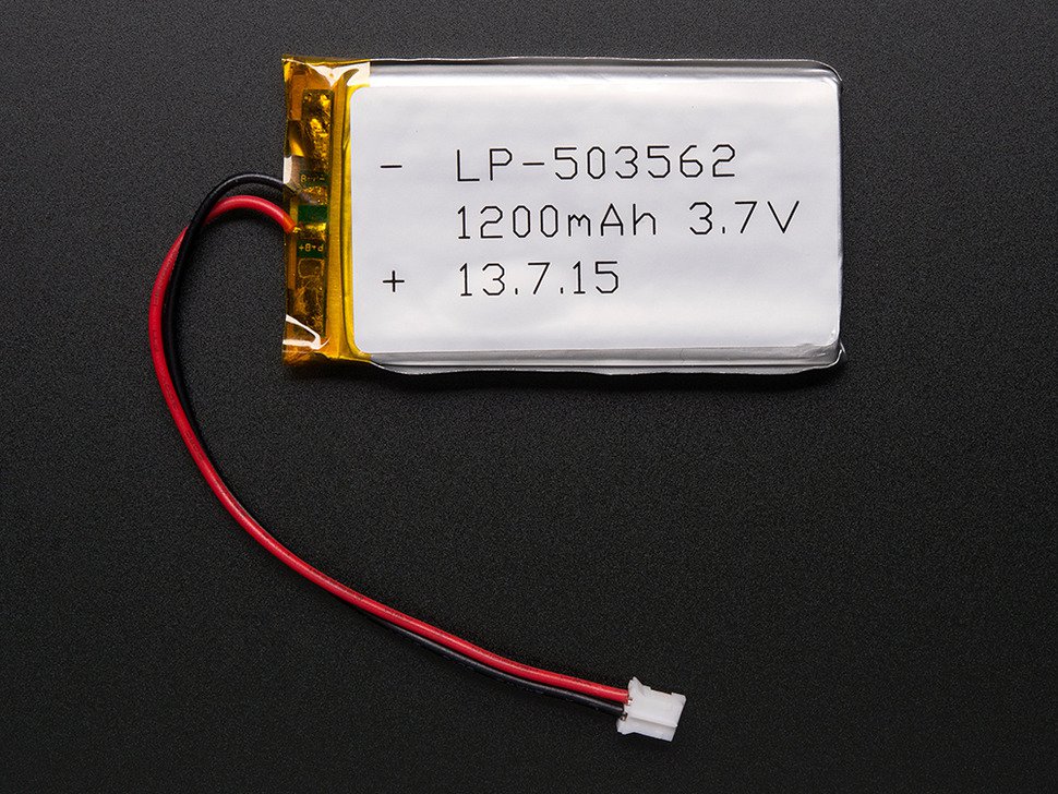
Powering our Bi.xel device To make it portable and usable everyone you want we are powering our device with a Lithium Ion Polymer Battery (3.7v 1200mAh) - also available via Adafruit.
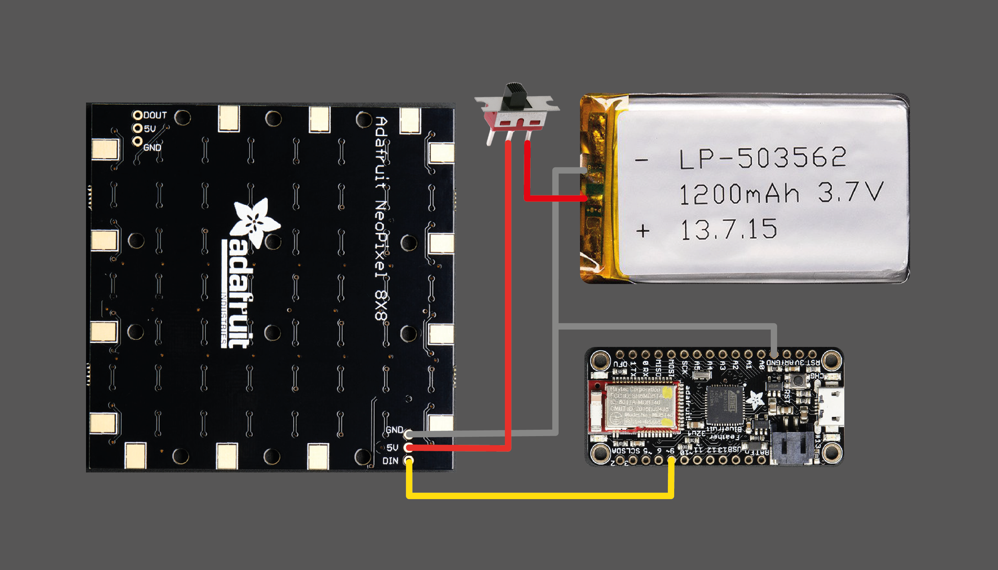
Wiring up of Bi.xel device So, let’s wire all parts together. To run the LEDs we have to connect the LED matrix with the Arduino Feather board. There are only 3 required connections to run the LED matrix: power, ground, and the Neopixel data pin. For this project, we will use the default Neopixel control pin, D6, on the Adafruit Feather 32u4 Bluefruit LE to control our LEDs.
To power our 64 LEDs we will use the Lithium Ion Polymer Battery and to turn our screen off a simple slide switch which connects and disconnects our power-source.
Driving Bi.xel device If you haven’t done it already, you have to download the Arduino IDE version 1.6.4 or higher. As a next step we have to set up our Bluefruit Feather Board for Arduino as described here. Next we have to install the boards with the Board Manager like described here.
Upload Arduino code To be able to communicate between our device and our smartphone, we have to upload the following Arduino code.
To avoid any errors, we have to download multiple libaries before copying in the Arduino code. Here more about Arduino libraries.
Spy.h
Softwareserial.h
Adafruit BLE Libraries
Adafruit_NeoPixel.h
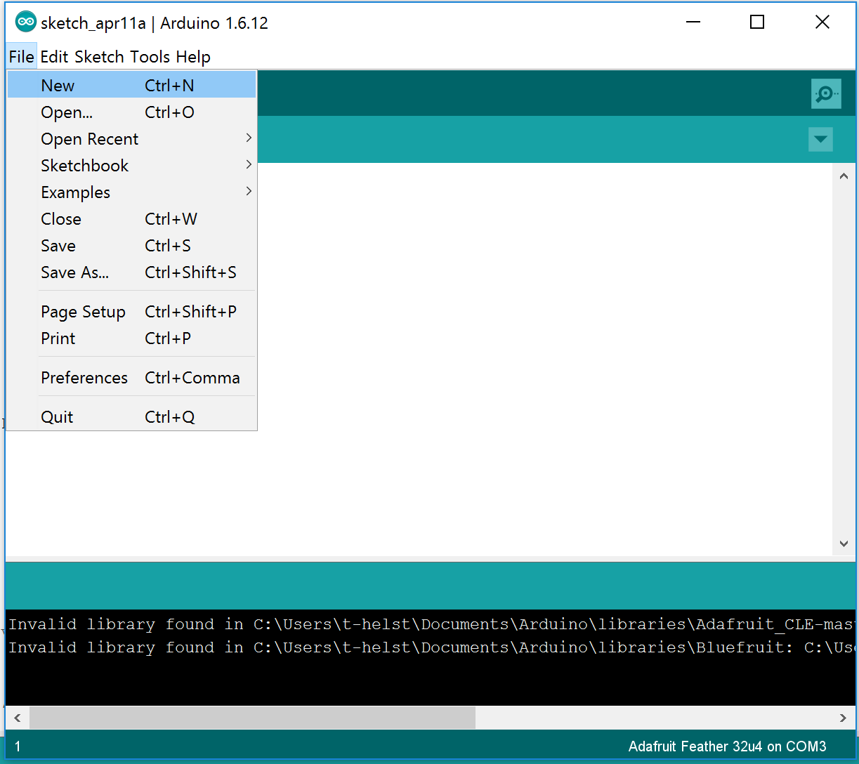
Now copy&paste the following code into a new sketch and save it.
// Include Bluetooth

#include <Arduino.h>
#include <SPI.h>
#include <EEPROM.h>
#if not defined (_VARIANT_ARDUINO_DUE_X_) && not defined (_VARIANT_ARDUINO_ZERO_)
#include <SoftwareSerial.h>
#endif

#include "Adafruit_BLE.h"
#include "Adafruit_BluefruitLE_SPI.h"
#include "Adafruit_BluefruitLE_UART.h"

#include "BluefruitConfig.h"

// Include NeoPixel
#include <Adafruit_NeoPixel.h>
#ifdef __AVR__
#include <avr/power.h>
#endif

// Include
#include "ArdPrintf.h"

// Config
#define FACTORYRESET_ENABLE      1

// Bluetooth
// ...hardware SPI, using SCK/MOSI/MISO hardware SPI pins and then user selected CS/IRQ/RST
Adafruit_BluefruitLE_SPI ble(BLUEFRUIT_SPI_CS, BLUEFRUIT_SPI_IRQ, BLUEFRUIT_SPI_RST);

// Neopixel
#define PIN            13   /* Pin used to drive the NeoPixels */

#define MAXCOMPONENTS  4
uint8_t *pixelBuffer = NULL;
uint8_t width = 0;
uint8_t height = 0;
uint8_t components = 3;     // only 3 and 4 are valid values
uint8_t stride;

//Adafruit_NeoPixel pixels = Adafruit_NeoPixel();
Adafruit_NeoPixel pixels = Adafruit_NeoPixel(64, PIN, NEO_GRB + NEO_KHZ800);

void setup()
{
  pixels.begin();

  //pixels.setPin(PIN);

  // Read the brightness
  uint8_t brightness = EEPROM.read(96);
  pixels.setBrightness(brightness);

  for(int i=0;i<64;i += 1){
      // Read the color
     uint8_t red = EEPROM.read((i*3)+i);
     uint8_t green = EEPROM.read((i*3)+i+1);
     uint8_t blue = EEPROM.read((i*3)+i+2);
    pixels.setPixelColor(i, red, green, blue); // blue
    pixels.show();
  }

  while (!Serial);  // required for Flora & Micro
  delay(500);

  Serial.begin(115200);
  Serial.println(F("Adafruit Bluefruit Neopixel Test"));
  Serial.println(F("------------------------------------"));

  // Initialise the module
  Serial.print(F("Initialising the Bluefruit LE module: "));

  if ( !ble.begin(VERBOSE_MODE) )
  {
    error(F("Couldn't find Bluefruit, make sure it's in CoMmanD mode & check wiring?"));
  }
  Serial.println( F("OK!") );

  // Factory Reset
  if ( FACTORYRESET_ENABLE )
  {
    /* Perform a factory reset to make sure everything is in a known state */
    Serial.println(F("Performing a factory reset: "));
    if ( ! ble.factoryReset() ) {
      error(F("Couldn't factory reset"));
    }
  }

  /* Disable command echo from Bluefruit */
  ble.echo(false);

  Serial.println("Requesting Bluefruit info:");
  /* Print Bluefruit information */
  ble.info();

  /* Wait for a connection before starting the test */
  Serial.println("Waiting for a BLE connection to continue ...");

  ble.verbose(false);  // debug info is a little annoying after this point!

  while ( !ble.isConnected() )
  {
    delay(10);
  }

  // Wait for the connection to complete
  delay(1000);

  Serial.println(F("CONNECTED!"));
  Serial.println(F("**********"));

  // Set module to DATA mode
  Serial.println( F("Switching to DATA mode!") );
  ble.setMode(BLUEFRUIT_MODE_DATA);

  Serial.println(F("******************************"));

  // Neopixels
  pixels.begin();
}

void loop()
{
  // Echo received data
  while ( ble.isConnected() )
  {
    int command = ble.read();

    switch (command) {
      case 'V': {   // Get Version
          commandVersion();
          break;
        }

      case 'S': {   // Setup dimensions, components, stride...
          commandSetup();
          break;
       }

      case 'C': {   // Clear with color
          commandClearColor();
          break;
      }

      case 'B': {   // Set Brightness
          commandSetBrightness();
          break;
      }

      case 'P': {   // Set Pixel
          commandSetPixel();
          break;
      }

      case 'I': {   // Receive new image
          commandImage();
          break;
       }

    }
  }
}

void swapBuffers()
{
  uint8_t *base_addr = pixelBuffer;
  int pixelIndex = 0;
  for (int j = 0; j < height; j++)
  {
    for (int i = 0; i < width; i++) {
      if (components == 3) {
        pixels.setPixelColor(pixelIndex, pixels.Color(*base_addr, *(base_addr+1), *(base_addr+2)));
      }
      else {
        Serial.println(F("TODO: implement me"));
      }
      base_addr+=components;
      pixelIndex++;
    }
    pixelIndex += stride - width;   // move pixelIndex to the next row (take into account the stride)
  }
  pixels.show();

}

void commandVersion() {
  Serial.println(F("Command: Version check"));
  sendResponse("Neopixel v1.0");
}

void commandSetup() {
  Serial.println(F("Command: Setup"));

  width = ble.read();
  height = ble.read();
  components = ble.read();
  stride = ble.read();
  neoPixelType pixelType;
  pixelType = ble.read();
  pixelType += ble.read()<<8;

  ardprintf("\tsize: %dx%d", width, height);
  ardprintf("\tcomponents: %d", components);
  ardprintf("\tstride: %d", stride);
  ardprintf("\tpixelType %d", pixelType );

  if (pixelBuffer != NULL) {
      delete[] pixelBuffer;
  }

  uint32_t size = width*height;
  pixelBuffer = new uint8_t[size*components];
  pixels.updateLength(size);
  pixels.updateType(pixelType);
  pixels.setPin(PIN);

  // Done
  sendResponse("OK");
}

void commandSetBrightness() {
  Serial.println(F("Command: SetBrightness"));

   // Read value
  uint8_t brightness = ble.read();

  // Write the brightness to memory
  EEPROM.write(96, brightness);

  // Set brightness
  pixels.setBrightness(brightness);

  // Refresh pixels
  swapBuffers();

  // Done
  sendResponse("OK");
}

void commandClearColor() {
  Serial.println(F("Command: ClearColor"));

  // Read color
  uint8_t color[MAXCOMPONENTS];
  for (int j = 0; j < components;) {
    if (ble.available()) {
      color[j] = ble.read();
      j++;
    }
  }

  // Set all leds to color
  int size = width * height;
  uint8_t *base_addr = pixelBuffer;
  for (int i = 0; i < size; i++) {
    for (int j = 0; j < components; j++) {
      *base_addr = color[j];
      base_addr++;
    }
  }

  // Swap buffers
  Serial.println(F("ClearColor completed"));
  swapBuffers();

  if (components == 3) {
    ardprintf("\tcolor (%d, %d, %d)", color[0], color[1], color[2] );
  }

  // Done
  sendResponse("OK");
}

void commandSetPixel() {
  Serial.println(F("Command: SetPixel"));

  // Read position
  uint8_t x = ble.read();
  uint8_t y = ble.read();

  // Read colors
  uint32_t pixelIndex = y*width+x;
  uint32_t pixelComponentOffset = pixelIndex*components;
  uint8_t *base_addr = pixelBuffer+pixelComponentOffset;
  for (int j = 0; j < components;) {
    if (ble.available()) {
      *base_addr = ble.read();
      base_addr++;
      j++;
    }
  }

  // Set colors
  if (components == 3) {
    uint32_t pixelIndex = y*stride+x;
    pixels.setPixelColor(pixelIndex, pixels.Color(pixelBuffer[pixelComponentOffset], pixelBuffer[pixelComponentOffset+1], pixelBuffer[pixelComponentOffset+2]));

    ardprintf("\tcolor (%d, %d, %d)", pixelBuffer[pixelComponentOffset], pixelBuffer[pixelComponentOffset+1], pixelBuffer[pixelComponentOffset+2] );

    // Write the color to the memory
    EEPROM.write(pixelIndex, pixelBuffer[pixelComponentOffset]);
    EEPROM.write(pixelIndex+1, pixelBuffer[pixelComponentOffset+1]);
    EEPROM.write(pixelIndex+2, pixelBuffer[pixelComponentOffset+2]);
  }
  else {
    Serial.println(F("TODO: implement me"));
  }
  pixels.show();

  // Done
  sendResponse("OK");
}

void commandImage() {
  ardprintf("Command: Image %dx%d, %d, %d", width, height, components, stride);

  // Receive new pixel buffer
  int size = width * height;
  uint8_t *base_addr = pixelBuffer;
  for (int i = 0; i < size; i++) {
    for (int j = 0; j < components;) {
      if (ble.available()) {
        *base_addr = ble.read();
        base_addr++;
        j++;
      }
    }

/*
    if (components == 3) {
      uint32_t index = i*components;
      ardprintf("\tp%d (%d, %d, %d)", i, pixelBuffer[index], pixelBuffer[index+1], pixelBuffer[index+2] );
    }
    */
  }

  // Swap buffers
  Serial.println(F("Image received"));
  swapBuffers();

  // Done
  sendResponse("OK");
}

void sendResponse(char *response) {
    ardprintf("Send Response: %s", response);
    ble.write(response, strlen(response)*sizeof(char));
}

// A small helper
void error(const __FlashStringHelper*err) {
  Serial.println(err);
  while (1);
}
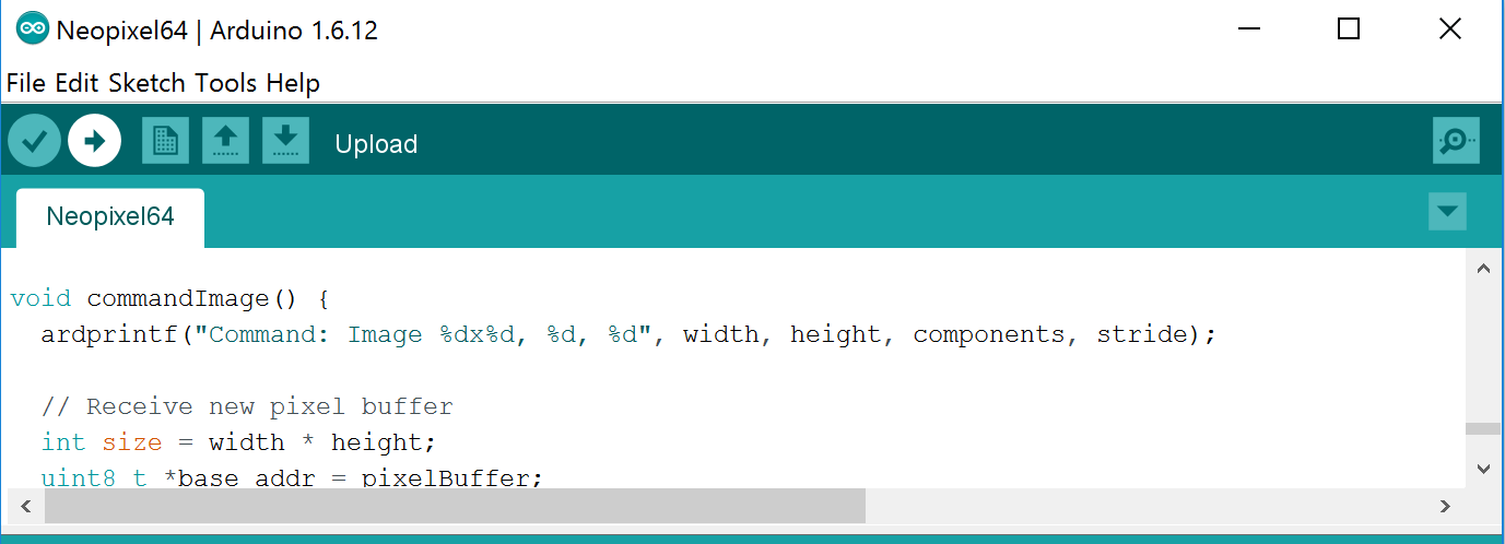
It’s time to upload your code onto your device. Plug in your device with a Micro-USB to USB cable into your laptop and choose the right port inside your Arduino window.
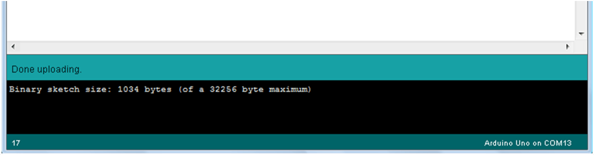
Click upload!
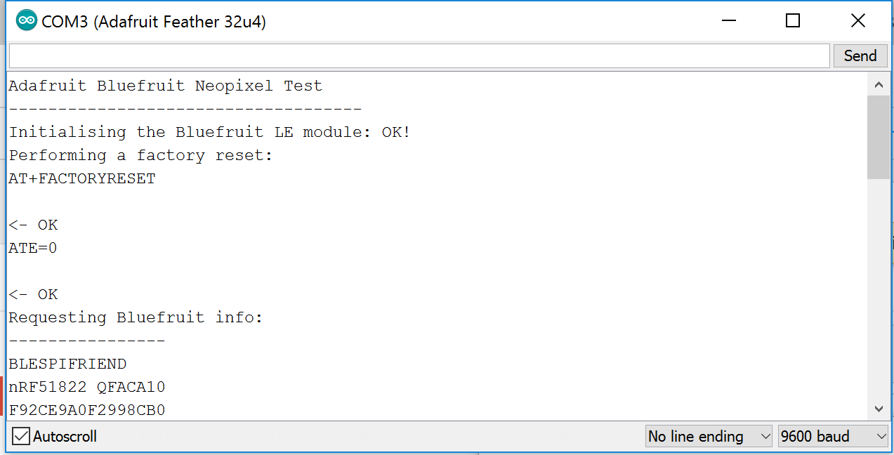
And wait till it got successfully uploaded. It should look like something like this.
App to control your pixels and to design your Bi.xels
Now let’s get started to be able to control the LEDs.First download the Adafruit Bluefruit LE Connect App on your smartphone. The app is available for iOS and Android.
Open in Arduino your serial monitor to get connected with your bi.xel device. It will show you if you are communicating and what.
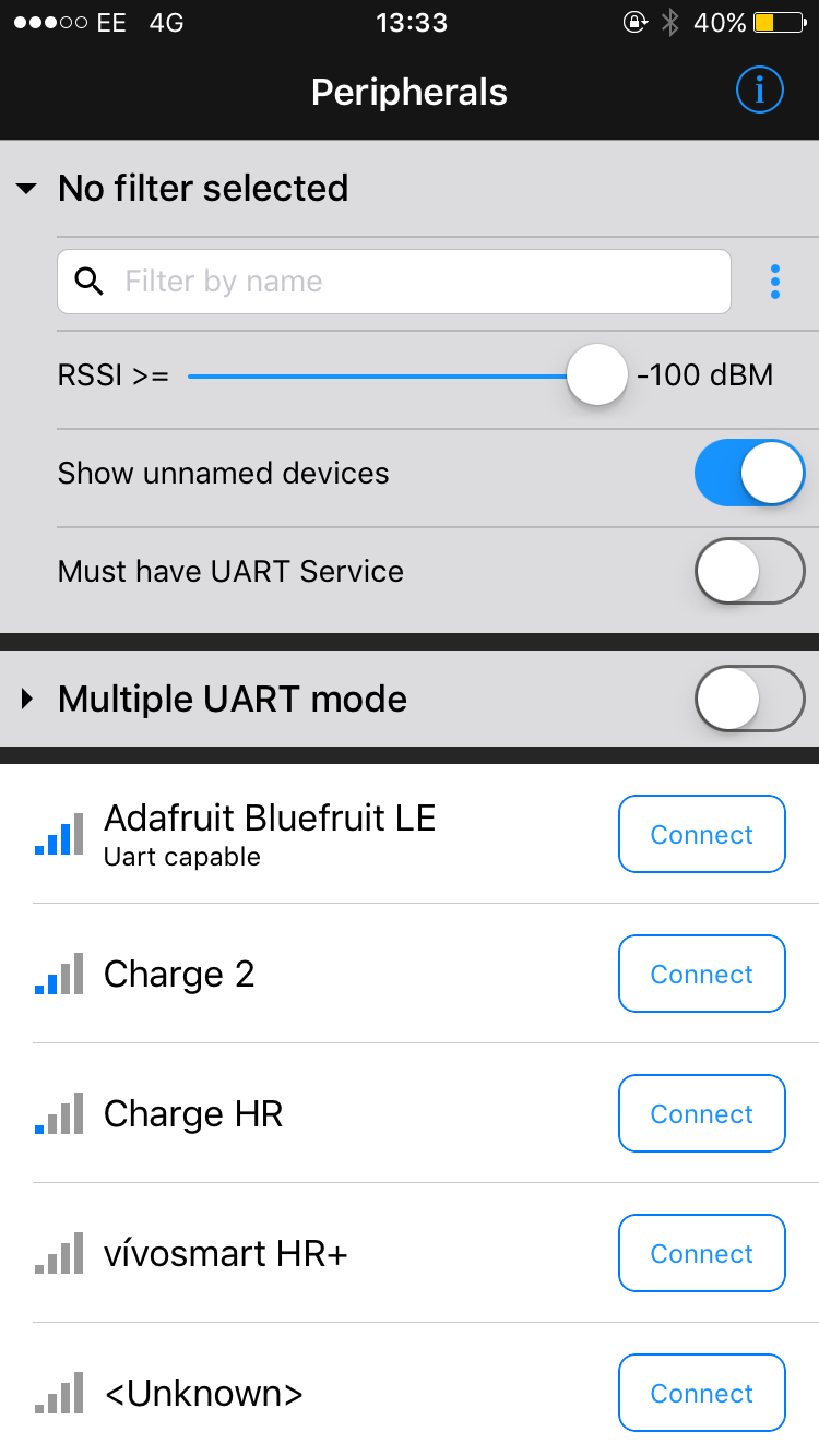
Next we will connect via the app to our device. Open the app and connect to your device Adafruit Bluefruit LE.
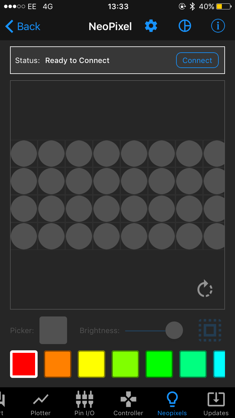
Choose the NeoPixel icon in the bottom line and press OK when it gives your a notice.
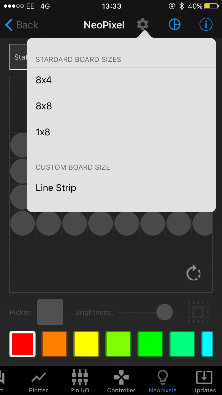
Next we have to choose the correct matrix layout. Click the settings button at the top, next to the word ‘NeoPixel’ and choose ‘8x8’.
Now press ‘Connect’ - all pixels should change to white now.
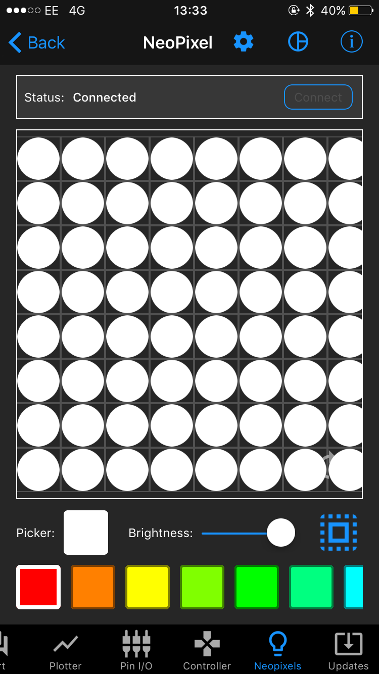
Now you are ready to control your pixels. To turn them off turn all to black.
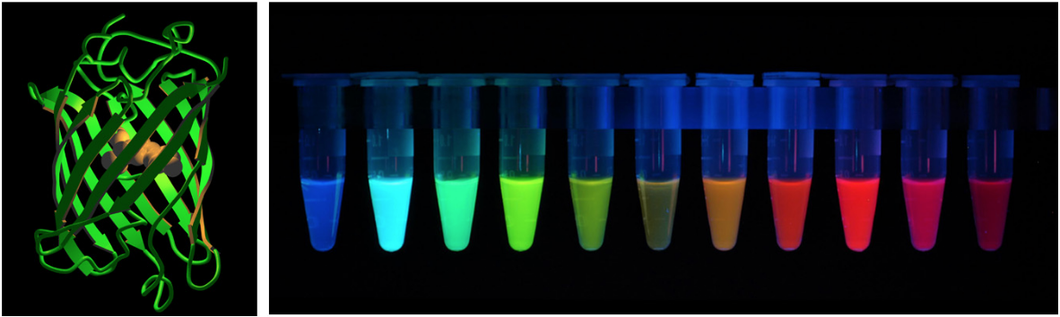
It is quite neat that the colors of the app are similar to different potential expressions with GfP. In our case we used green for a green fluorescent GfP. Here the link to the cell-free part of our tutorial.
After choosing your design you can disconnect your device from your laptop and the LEDs will stay on, but you won’t be able to change them anymore till you connect again to your laptop. Use the switch if you want to turn the LEDs off.
Cover for Bi.xels to make it a portable display and learning device
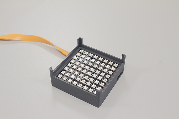
To make it to a portable functional device we designed a cover for you to be able to use it with standard PCR strips.
To protect and hide your electronic parts you can simply 3D-print with an objet printer or a cheaper SLA printer the part. You can download the .stl file here.
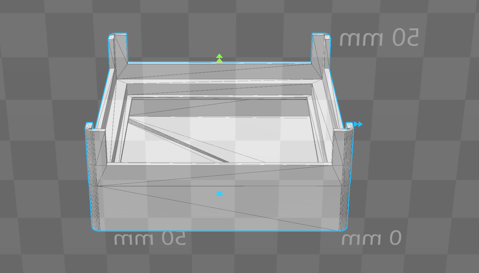
The Bluefruit feather and battery fits easily in the lower part and the LED matrix fits perfectly on top. On the sides you have an opening to access the plug for the board and the be able to mount your slide switch.
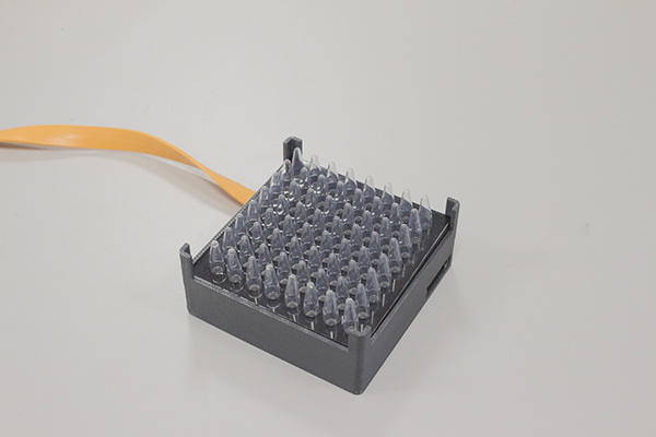
The corners are higher than the rest to clip our PCR matrix on top of the device. For this we created a simple template that you can lasercut out of an acrylic plastic sheet (we used 3mm thick acrylic). The template allows you to easily clip in standard PCR strips and will align your PCR tubes with the LEDs. Here the lasercut file.
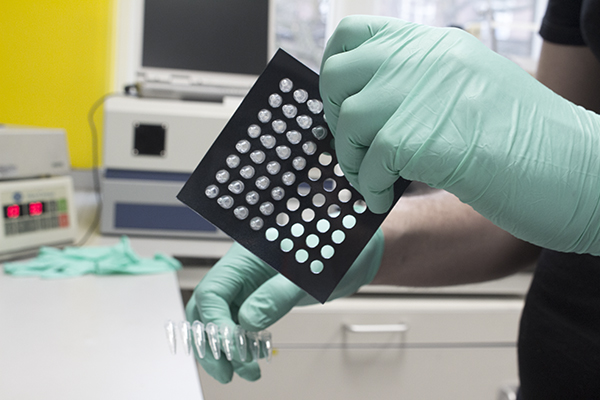
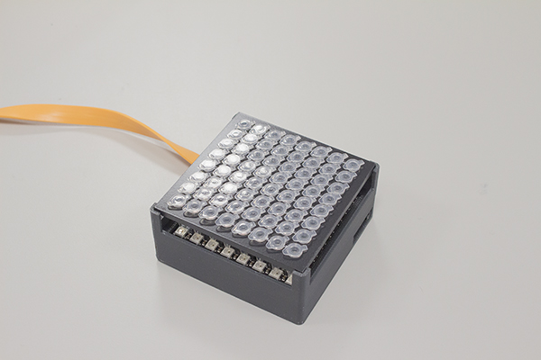
This allows you to extend the functions of the device such as for educational purposes and to guide you through your protocol.
Here some additional videos of the device in action.!
Video1 - Controlling LED matrix
Video2 - The X factor
Video3 - Using LED for education purposes (credit Mihais Delmans, Haseloff Lab)